Артикул: rx7037
Бренд: Bosch Rexroth
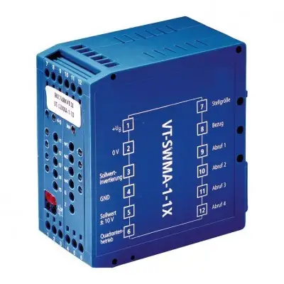
Серия компонентов 1X. Аналоговая, модульная конструкция. Для управления клапанами со встроенной электроникой
Общая информация. Модуль командных значений устанавливается на DIN-рейки согласно EN 60715. Электрическое подключение осуществляется с помощью винтовых клемм. Модуль работает от напряжения 24 В пост. тока. Блок питания [1] обеспечивает внутренне требуемые положительные и отрицательные напряжения питания. При работе блока питания горит зелёный светодиод («power»). Внутреннее командное значение. Внутреннее командное значение формируется из внешнего сигнала командного значения, поданного на дифференциальный вход [2], вызванного сигнала и сигнала смещения (потенциометр нулевой точки «Z» [3]). Внешний сигнал командного значения может изменяться потенциометром «G» (ослабитель амплитуды [4]) от 0 % до прибл. 110 %. Вызовы командных значений. Вызывные сигналы w1 … w4 [5] также могут настраиваться в диапазоне от 0 % до 110 %. Вызывные сигналы w1 и w2 имеют положительную, а вызывные сигналы w3 и w4 — отрицательную полярность. Это позволяет реализовать два движения вперёд и два реверсивных движения гидравлического привода без дополнительной схемотехники. Для применений, требующих более двух сигналов одинаковой полярности, предусмотрена инверсия командного значения [6]. Если она активирована, например, вместе с вызовом 3, вызывной сигнал w3 также обеспечивает положительную управляющую переменную. Одновременно возможен только один вызов. При одновременной активации нескольких вызовов действует: вызов «1» имеет самый низкий приоритет, вызов «4» — самый высокий [7]. Распознавание квадранта. При активированном распознавании квадранта [8] электроника автоматически определяет полярность [9] и любые изменения (нарастание/спад) [10] управляющей переменной и назначает время рампы текущему состоянию сигнала. Время рампы | Полярность управляющего выхода | Изменения сигнала в направлении…. t1 + Максимальное значение → 0 % → Максимальное значение (+). t2 + 0 % → Максимальное значение (+) → 0 %. t3 – Максимальное значение → 0 % → Максимальное значение (–). t4 – 0 % → Максимальное значение (–) → 0 %. Пока сигнал изменяется, светодиод, назначенный текущей рампе, горит. Вызовы времени рампы [11]. При деактивированном распознавании квадранта каждому командному значению назначается отдельное время рампы «t1» … «t4»
Бесплатная доставка по РФ при заказе от 50 000 р.
Компания ООО «Индатэк» работает с юридическими лицами по всей территории России. Каждый день мы осуществляем доставку заказов от Калининграда до Владивостока. Вместе с отгруженным товаром, клиент получает бухгалтерские и гарантийные документы на 12 месяцев. По желанию, вы можете продлить срок гарантии.
При заказе от 50000 руб.
Цены указаны с НДС
И постгарантийное обслуживание