Артикул: rx7314
Бренд: Bosch Rexroth
| Параметр | Значение |
|---|---|
| Серия высокого давления Типоразмер | 25 |
| Серия компонентов 3X Максимальное рабочее давление | 700 бар |
| Максимальный расход | 3500 л/мин |
| Площадь на седле клапана A1 определяется как | 100% |
| A2, реализуемая ступенчатостью, составляет | 0% |
| Для цепей обратного клапана доступен | 7% |
| Пример: Управляющая крышка: Тип LFT | 25 |
| DBW2-3X/1000J3F Картриджный клапан: Тип LCT | 25 |
| DB40D-3X/700F Код типа | 01 02 |
| LCT DB | 40 |
| D 3X / | 700 |
| F 01 Картриджный клапан LCT | 02 |
| Типоразмер | 25 25 |
| Типоразмер | 32 32 |
| Типоразмер | 40 40 |
| Типоразмер | 50 50 |
| A1 = | 100% |
| A2 = | 0% |
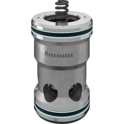
… 50 Особенности Уплотнение вала по умолчанию Специальные управляющие золотники для цепи обратного клапана Описание изделия Двухходовые картриджные клапаны представляют собой элементы, разработанные для компактной блочной конструкции. Картриджный клапан типа LCT вставляется в специальное приемное отверстие в управляющем блоке и закрывается управляющей крышкой типа LFT. Управляющая крышка устанавливает соединение между пружинной камерой картриджного клапана и пилотными клапанами. Это позволяет реализовать функции давления, направления и дросселирования — также в комбинации. Основными компонентами двухходовых картриджных клапанов являются картриджный клапан (8) и управляющая крышка (2) с различной функциональностью. Картриджный клапан (8) состоит из гнезда (3) с уплотнительным пакетом (4), управляющего золотника (5) и замыкающей пружины (6). Управляющая крышка (2) уплотняет картриджный клапан снаружи. Помимо простых функций управляющей крышки с внешней подачей пилотного масла, исполнение "LFT . DBW2" также подходит для сложных функций переключения благодаря стандартной присоединительной поверхности для направленного клапана. Присоединительная поверхность всегда закрыта герметично (1). Могут подключаться подходящие переключающие и пропорциональные сервоклапаны. Давление разгрузки устанавливается на картридже (7). Из-за конструктивных требований некоторые исполнения управляющих крышек имеют фитинги высокого давления, выходящие наружу. Им назначено дренажное отверстие L для индикации утечки на фитинге высокого давления. Эти порты не подходят для внешней подачи пилотного масла. Функция Пассивно управляемые двухходовые картриджные клапаны работают в зависимости от соотношения давлений в рабочих портах A и B. В результате для функции реализуются три важные поверхности под давлением A1, A2, A3. . В зависимости от исполнения, кольцевая площадь , или 5 от площади A1. Площадь A3 идентична сумме площадей A1 + A2. При функции давления площадь 0. Соответственно, площадь A3 = A1. 7%-ный управляющий золотник с внутренней обратной связью по давлению. Таким образом, конструкция блока становится менее сложной, так как не требуется внешняя обратная связь по давлению в пружинную камеру через порт пилотного масла X (см. "Примеры схем"). В общем случае действует следующее: Площади A1 и A2 эффективны в направлении открытия. Площадь A3 и пружина эффективны в направлении закрытия. Направление действия результирующей силы от открывающих и закрывающих сил определяет рабочее положение двухходового картриджного клапана. 03 04 05 06 07 08 Конструкция управляющего золотника (соотношение площадей см. "описание изделия") 03 ; A2 = 0% DB Давление открытия. Описание: 2-ходовые картриджные клапаны представляют собой элементы, разработанные для компактной блочной конструкции
Бесплатная доставка по РФ при заказе от 50 000 р.
Компания ООО «Индатэк» работает с юридическими лицами по всей территории России. Каждый день мы осуществляем доставку заказов от Калининграда до Владивостока. Вместе с отгруженным товаром, клиент получает бухгалтерские и гарантийные документы на 12 месяцев. По желанию, вы можете продлить срок гарантии.

При заказе от 50000 руб.
Цены указаны с НДС
И постгарантийное обслуживание