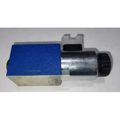
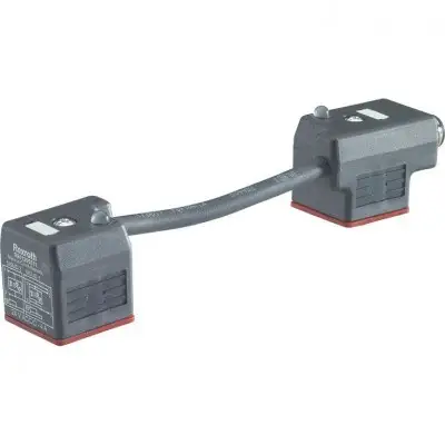
Артикул: rx7673
Бренд: Bosch Rexroth
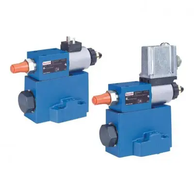
Типоразмер 10, 25. Серия 6X. Макс. рабочее давление 315 бар. Расход, макс. 300 л/мин
Клапаны типа DRE(M) являются редукционными клапанами с пилотным управлением. Они используются для снижения рабочего давления. Эти клапаны в основном состоят из клапана пилотного управления (1) с пропорциональным электромагнитом (2), главного клапана (3) с главным золотниковым узлом (4), а также опционального обратного клапана (5). Тип DRE.. Давление в канале A задаётся в зависимости от командного значения через пропорциональный электромагнит (2). В исходном положении – без давления в канале B – пружина (17) удерживает главный золотник (4) в его исходном положении. Соединение от канала B к A закрыто. Таким образом предотвращается пусковой скачок. Давление в канале A действует на поверхность (7) главного золотника через отверстие (6). Pilot oil отбирается из канала B и поступает через отверстие (8) к регулятору постоянного расхода (9), который поддерживает расход управления постоянным независимо от перепада давления между каналами A и B. От регулятора постоянного расхода (9) поток управления поступает в пружинную камеру (10), через отверстия (11) и (12) через седло клапана (13) в канал Y (14, 15, 16) и оттуда в обратную линию. Требуемое давление в канале A задаётся на соответствующем усилителе. Пропорциональный электромагнит перемещает конус клапана (20) в направлении седла клапана (13) и ограничивает давление в пружинной камере (10) до заданного значения. Если давление в канале A ниже заданного командного значения, более высокое давление в пружинной камере (10) перемещает главный золотник вправо. Соединение от B к A открывается. Если заданное давление в A достигнуто, силы на главном золотнике уравновешены – главный золотник находится в положении регулирования. Давление в канале A • Поверхность золотника (7) = давление в пружинной камере (10) • Поверхность золотника – усилие пружины (17). Если в стоящем столбе рабочей жидкости (например, поршень цилиндра на упоре) давление в A должно быть снижено, (например) на электронике управления задаётся более низкое командное значение, и таким образом задаётся более низкое давление, которое немедленно присутствует в пружинной камере (10). Более высокое давление в A, действующее на поверхность (7) главного золотника, отжимает главный золотник до упора в резьбовую заглушку (18). Соединение A к B заблокировано, а A к Y открыто. Усилие пружины (17) теперь противодействует гидравлической силе, действующей на поверхность (7) главного золотника. В этом положении главного золотника рабочая жидкость может поступать из канала A через регулирующую кромку (19) в Y и в обратную линию. Когда давление в A снизилось до
. Функция: Номинальное давление 50 бар 3) 70 бар Номинальное давление 100 бар 130 бар Номинальное давление 200 бар 230 бар Номинальное давление 315 бар 350 бар Контрольный расход, л/мин 0Бесплатная доставка по РФ при заказе от 50 000 р.
Компания ООО «Индатэк» работает с юридическими лицами по всей территории России. Каждый день мы осуществляем доставку заказов от Калининграда до Владивостока. Вместе с отгруженным товаром, клиент получает бухгалтерские и гарантийные документы на 12 месяцев. По желанию, вы можете продлить срок гарантии.

При заказе от 50000 руб.
Цены указаны с НДС
И постгарантийное обслуживание