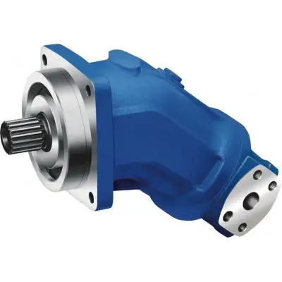
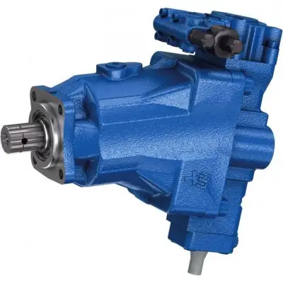
Артикул: rx7767
Бренд: Bosch Rexroth
| Параметр | Значение |
|---|---|
| Типоразмер | 1, 2. |
| Типоразмер | 16 |
| Номинальное давление | 290 бар |
| Максимальное давление | 320 бар |
| Рабочий объём | 15,9 |
Фиксированный рабочий объём. … 79. . . … 79,3 см³
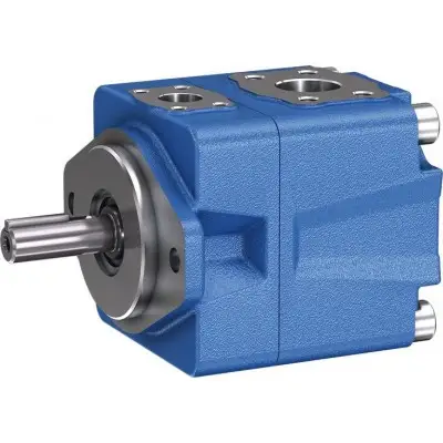
Функциональная схема. Гидравлические насосы типа PVH представляют собой пластинчатые насосы с постоянным рабочим объёмом. Ротор (2), вращающийся в статорном кольце (3), установлен на зубчатом профиле приводного вала (1). В пазах ротора размещены пластины (4), которые под действием центробежной силы при вращении ротора прижимаются к внутренним поверхностям статорного кольца. Рабочие камеры уплотнены с боков управляющими дисками (5). Благодаря двухэксцентриковой конструкции статорного кольца образуются две напорные камеры, расположенные напротив двух всасывающих камер, что обеспечивает гидравлическую разгрузку вала. Таким образом, вал передаёт только крутящий момент. Пластины частично разгружаются при прохождении через зону всасывания. Эта разгрузка снижает износ и обеспечивает высокий КПД. Простым снятием крышки (6) насосная вставка (состоящая из ротора, пластин, статорного кольца и управляющих дисков) может быть извлечена без необходимости демонтажа корпуса (7) с несущей конструкции насоса. Это обеспечивает быстрое техническое обслуживание и ремонт насоса. Сечение. PVH.
01 02 03 04 05 06 07 08 09 10 11 12. PV H – 1X / 15 *. Тип. 01 Пластинчатый насос, фиксированный рабочий объём PV. Серия. 02 Насос высокого давления H. Типоразмер BG. 03 BG1 1. BG2 2. Серия. 04 Серия 10 … 19 (10 … 19: неизменные установочные и присоединительные размеры) 1X. Типоразмер (NG). 016 020 023 025 028 032 035 041 045 050 058 064 070 079. 05 Типоразмер 1 ● ● ● ● ● ● ● – – – – – – –. Типоразмер 2 ● ● ● ● ● ● ● ● ● ● ● ● ● ●. Направление вращения. 06 Вид на приводной вал: правое R. против часовой стрелки L. Приводной вал. 07 Цилиндрический вал с призматической шпонкой DIN 6885 A. Шлицевой вал SAE J744 с эвольвентным зубчатым профилем по ANSI B92.1a J. Присоединение трубопроводов. 08 Всасывающий и напорный патрубки по SAE J518; стандартный ряд давлений 15. Расположение всасывающего патрубка (вид на приводной вал). 09 Сверху (0° от напорного патрубка) D. Снизу (180° от напорного патрубка) U. Справа (90° вправо от напорного патрубка) R. Слева (90° влево от напорного патрубка) L. Материал уплотнений. 10 NBR (бутадиен-нитрильный каучук) M. FKM (фторкаучук) V. Монтажный фланец. 11 101-2 (SAE-B) B. Прочее по запросу *. Дополнительные сведения. 12 Информация в виде текста *. ● = Доступно – = Недоступно.
| Параметр | Значение |
|---|---|
| Типоразмер | 1 2. |
| Типоразмер | 16 20 |
| Частота вращения 1) n об/мин | 600 |
23 25 28 32 35 16 20 23 25 28 32 35 41 45 50 58 64 70 79. Серия 1X. Тип монтажа Фланцевое крепление. .. 3600 600 .. 30 600 .. 3600
Бесплатная доставка по РФ при заказе от 50 000 р.
Компания ООО «Индатэк» работает с юридическими лицами по всей территории России. Каждый день мы осуществляем доставку заказов от Калининграда до Владивостока. Вместе с отгруженным товаром, клиент получает бухгалтерские и гарантийные документы на 12 месяцев. По желанию, вы можете продлить срок гарантии.
При заказе от 50000 руб.
Цены указаны с НДС
И постгарантийное обслуживание