Артикул: rx7844
Бренд: Bosch Rexroth
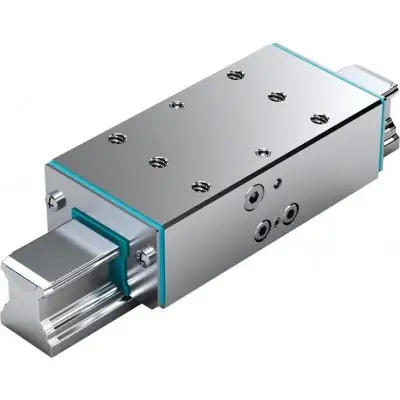
| Параметр | Значение |
|---|---|
| Компактная конструкция, совместимая с DIN | 645 |
| Плавно регулируемое давление от | 50 |
Очень высокие усилия зажима в осевом направлении Динамическая и статическая стабилизация в осевом направлении Зажимные и тормозные элементы с гидравлическим приводом Особенности Возможность использования на всех шариковых направляющих SNS Резьба с двух сторон для гидравлического подключения Прочный жёсткий стальной корпус с химическим никелированием Высокая точность позиционирования до 150 бар Встроенное всестороннее уплотнение Специальная технология мембранного давления для максимальной функциональной надёжности без потерь давления и утечек Встроенные профили с геометрическим замыканием и большой площадью контакта для максимальной осевой жёсткости 10 миллионов циклов зажима (значение B10d)
Принцип работы Гидравлическое давление: 50–150 бар Зажим под давлением Крупногабаритные зажимные профили прижимаются гидравлическим маслом непосредственно к боковым поверхностям шариковой направляющей по поршневому принципу. Гидравлическое давление: 0 бар Разжим под действием пружины Предварительно натянутая возвратная пружина обеспечивает короткое время разжима.
| Параметр | Значение |
|---|---|
| Общие технические данные Типоразмер | 25 30 |
| Усилие зажима 1) Н | 1600 2 |
| Вытесняемый объём 4) см³ | 0,6 0,7 |
| Масса кг | 1,22 2,09 |
| Условия эксплуатации Типоразмер | 25 30 |
| ISO-VG | 68 |
| При 100 бар 3) При | 150 бар |
| G1 с двух сторон для типоразмеров | 25 |
35 45 55 65 ) 3000 2) 3500 2) 7400 2) 13700 3) 22700 3) 1,1 1,8 2,4 3,8 Макс. рабочее гидравлическое давление бар 100 150 110 150 2,02 4 6,1 14,4 35 45 55 65 Допустимая температура окружающей среды (мин .. макс) 0 °C .. +70 °C 1) Проверка проводится в смонтированном состоянии со смазанным слоем ( ). Допустимые усилия зажима см. «Технические данные и расчёты». 2) 4) На один зажим Технические данные и расчёты Области применения Зажим тяжёлых погрузочно-разгрузочных систем зажим столов станков тяжелонагруженных обрабатывающих центров Размеры а) Гидравлическое подключение*) G1 с двух сторон б) Гидравлическое подключение*) –30 в) Кроме того, необходимо использовать оба крепёжных отверстия! *) Требуется только одно подключение. Все подключения заглушены при поставке
Типоразмер 25 30 35 45 55 65 A мм 48 60 70 86 100 126 B1 мм 92 103,5 120,5 155 184 227 B3max мм 102,3 115,4 134 170 201 256 E1 мм 35 40 50 60 75 76 E2 мм 50 60 72 80 95 120 F мм 8 9 12 15 16 20 G1 3 Verstellelemente 1/8" 1/4" H мм 36 42 48 60 70 90 H1 мм 29,5 35 40 50 57 76 N3 мм 8 13 15 18 21 S2 M6 M8 M10 M12 M16 Монтаж Указания по монтажу Упорные поверхности можно использовать с двух сторон. Обеспечьте жёсткость несущей конструкции. Соблюдайте инструкцию по монтажу перед вводом в эксплуатацию. Проверьте равномерность прилегания уплотнительных кромок передних уплотнений к шариковой направляющей. При необходимости выровняйте. Техническое обслуживание load error Загрузки Profilschienenführungen Руководство | R320103885 | 2016-09-01 | Немецкий | PDF | 11,4 МБ Группы продуктов: Linear guides Sistema de guias lineares Руководство | R320103885_PT | 2016-09-01 | Португальский | PDF | 11,3 МБ Группы продуктов: Linear guides Sistemas de guiado lineal Руководство | R320103885_ES | 2016-09-01 | Испанский | PDF | 11,4 МБ Группы продуктов: Linear guides Guide profilate Руководство |
Бесплатная доставка по РФ при заказе от 50 000 р.
Компания ООО «Индатэк» работает с юридическими лицами по всей территории России. Каждый день мы осуществляем доставку заказов от Калининграда до Владивостока. Вместе с отгруженным товаром, клиент получает бухгалтерские и гарантийные документы на 12 месяцев. По желанию, вы можете продлить срок гарантии.
При заказе от 50000 руб.
Цены указаны с НДС
И постгарантийное обслуживание