Артикул: rx8133
Бренд: Bosch Rexroth
| Параметр | Значение |
|---|---|
| Аналоговые выходные сигналы (Sin | 1 В |
| Цифровые выходные сигналы (TTL | 1 мкм |
пик-пик). , 5 мкм, 10 мкм)
| Параметр | Значение |
|---|---|
| Аналоговые выходные сигналы, синусоидальные сигналы | 1 В |
| A и B сдвинуты по фазе на | 90° |
| Амплитуда сигнала: A, B = | 1 В |
| Z0 = | 120 |
| RA = | 27,40 |
| Ом RRI = 0 Ом Z0 = | 120 |
| Ом Ucom = | 1,65 В |
| Они сдвинуты по фазе на | 90° |
| Uhigh > | 2 В |
| Ulow < | 0,8 В |
| Время переключения составляет ≤ | 100 |
| Z0 = | 120 |
| I2 1 | 4 2,0 |
| I3 5 | 20 5,0 |
| I4 10 | 40 5,0 |
| Напряжение питания | 4,75 |
| Потребляемый ток | 1 В |
| В: 300 мА | 1 В |
| В: 170 мА; TTL/5 В | 350 мА |
| TTL/12 В | 190 мА |
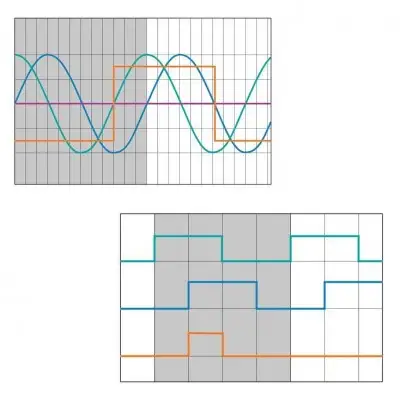
пик-пик (опция I1). Инкрементальные сигналы. Синусоидальные инкрементальные сигналы друг относительно друга и имеют типичную амплитуду сигнала пик-пик. пик-пик (±0,). Показанная последовательность выходных сигналов (B с фазовым отставанием от A) относится к движению сканера в положительном направлении счёта (см. график). Сигнал референтной метки. Дифференциальный сигнал референтной метки RI имеет амплитуду около -0,7 В в неактивном состоянии (низкий уровень). В активном состоянии (высокий уровень) амплитуда составляет +0,7 В. Обозначения: A, B синусоидальные инкрементальные сигналы RI сигнал референтной метки. 1 Период сигнала (40 мкм). 2 Перемещение. Схема интерфейса для аналоговых выходных сигналов. Указанные значения амплитуды действительны при работе с оконечным резистором Ом. . 1 сканер. 2 электроника обработки сигнала. Цифровые выходные сигналы, прямоугольные выходные сигналы TTL через встроенный блок интерполяции (опции I2, I3, I4). Инкрементальные сигналы. Цифровые инкрементальные сигналы A и B соответствуют стандарту EIA/TIA-422-A. и имеют следующие уровни сигнала:. . нс при ёмкостной нагрузке ≤ 1000 пФ. Сигнал референтной метки. Дифференциальный сигнал референтной метки RI имеет те же электрические характеристики, что и инкрементальные сигналы. Указанные значения амплитуды действительны при работе с оконечным резистором Ом (см. схему интерфейса). На графике показаны: A, B и полный дифференциальный RI для движения в положительном направлении счёта. 1 период сигнала. 2 Перемещение. 3 Расстояние между фронтами. Разрешение. Измерительные системы с цифровыми выходными сигналами доступны с разрешениями 1 мкм, 5 мкм и 10 мкм. Опция Разрешение (расстояние между фронтами) Период сигнала Макс. скорость сканера. (мкм) (мкм) (м/с). . . . до 12,6 В (на разъёме). Защита от перенапряжения: макс. 18 В пост. тока. 1 Впик-пик/5 1 Впик-пик/12
Интегрированная измерительная система IMS для шариковых и роликовых направляющих / Инструкция по электрическим интерфейсам / только PDF. Руководство | R320103166_EN | 01.10.2017 | Английский | PDF | 2,4 МБ. Группы изделий: Интегрированные измерительные системы. Интегрированная измерительная система IMS для шариковых и роликовых направляющих. Руководство | R320103262_EN | 01.07.2020 | Английский | PDF | 1,8 МБ. Группы изделий: Интегрированные измерительные системы. Каталог «Интегрированная измерительная система IMS для шариковых и роликовых направляющих». Каталог | R999000487 | 01.06.2020 | Английский | PDF | 2,7 МБ. Группы изделий: Шариковые направляющие, Роликовые направляющие, Интегрированные измерительные системы. Каталог «Интегрированная измерительная система IMS для шариковых и роликовых направляющих»
Бесплатная доставка по РФ при заказе от 50 000 р.
Компания ООО «Индатэк» работает с юридическими лицами по всей территории России. Каждый день мы осуществляем доставку заказов от Калининграда до Владивостока. Вместе с отгруженным товаром, клиент получает бухгалтерские и гарантийные документы на 12 месяцев. По желанию, вы можете продлить срок гарантии.
При заказе от 50000 руб.
Цены указаны с НДС
И постгарантийное обслуживание