Артикул: rx8155
Бренд: Bosch Rexroth
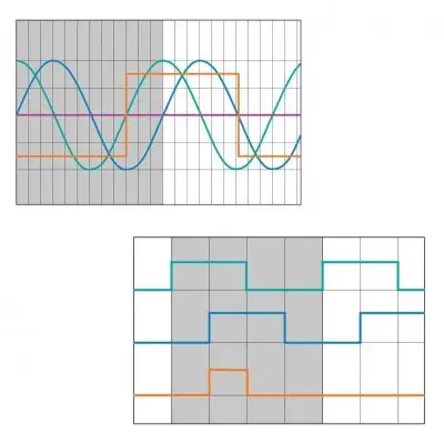
Электрический интерфейс, инкрементальный: аналоговые синусоидальные сигналы 1 В (размах). Электрический интерфейс, инкрементальный: цифровой прямоугольный выходной сигнал TTL
| Параметр | Значение |
|---|---|
| Аналоговый интерфейс | 1 В |
| A и B сдвинуты по фазе на | 90° |
| Период сигнала | 1000 мкм |
| I9 1000 | 5,0 |
| Z0 = | 120 |
| Z0 = | 120 |
| Ucom = | 2,5 В |
| TTL, разрешение | 10 мкм |
| Они сдвинуты по фазе на | 90° |
| Uhigh > | 2 В |
| Ulow < | 0,8 В |
| Z0 = | 120 |
| I4 10 | 40 1,0 |
| Напряжение питания | 10 |
| В (размах) при | 12 В |
| В (размах) при | 24 В |
| TTL при | 12 В |
| TTL при | 24 В |
Функциональная безопасность – Safe Motion. Пригодность IMScompact для функциональной безопасности в общей системе (электрический сигнальный тракт и механическая интеграция) в настоящее время находится в стадии подготовки. По этой причине механическое подключение IMScompact должно оцениваться соответствующим конструктором и/или инженером-машиностроителем с учётом аспектов безопасности, а результаты должны использоваться при анализе опасностей. Для применений с функциональной безопасностью магнитная лента должна быть всегда вклеена. Соответствующие исполнения IMScompact в настоящее время готовятся. Электрический интерфейс, инкрементальный: аналоговые синусоидальные сигналы (размах) (опция I9). 1 В (размах) (опция I9) предназначен для высокодинамичного регулирования положения линейных двигателей, ремённых или винтовых передач. Синусоидальные инкрементальные сигналы относительно друг друга и имеют типовую амплитуду сигнала 1 В (размах). 1) . 2) Перемещение. Опция Период сигнала Макс. скорость сканера Макс. скорость возврата в исходное положение. (мкм) (м/с) (м/с). ≤ 0,5. На графике показаны: A, B — синусоидальные инкрементальные сигналы. RI — сигнал референтной метки. A, B и полный дифференциальный RI для движения в положительном направлении счёта. Показанная последовательность выходных сигналов (B с отставанием по фазе от A) действует для движений измерительной головки в положительном направлении счёта. Дифференциальный сигнал референтной метки RI имеет амплитуду ок. -0,7 В в неактивном состоянии (low). В активном состоянии (high) амплитуда составляет +0,7 В. Указанные значения амплитуды действительны для работы с оконечным резистором Ом. 1) Сканер. 2) Электроника обработки сигнала. Ом. . Электрический интерфейс, инкрементальный: цифровой прямоугольный выходной сигнал (опция I4). Цифровой интерфейс TTL (опция I4) используется для отображения положения или передачи положения на программируемые логические контроллеры или дисплеи измеряемых значений. Цифровые инкрементальные сигналы A и B соответствуют стандарту EIA/TIA-422-A. и имеют следующие уровни сигнала: ; . Дифференциальный сигнал референтной метки RI имеет те же электрические характеристики, что и инкрементальные сигналы. Амплитуды действительны для работы с оконечным резистором Ом. 1) Период сигнала. 2) Перемещение. 3) Расстояние между фронтами. Опция Разрешение (расст. между фронтами) Период сигнала Макс. скорость сканера Макс. скорость возврата. (мкм) (мкм) (м/с) (м/с). ≤ 0,5. .. 30 В пост. тока. Потребляемая мощность. 1 : 19,5 мА. 1 : 11,3 мА. : 51,0 мА. : 28,5 мА. Электрический интерфейс, абсолютный: в подготовке
IMScompact integrated measuring system for BSHP ball rail system. Manual | R320103196_EN | 2019-12-01 | English | PDF | 2.5MB. Product Groups: Integrated measuring systems. R999001485 Integrated measuring system IMScompact. 001
Бесплатная доставка по РФ при заказе от 50 000 р.
Компания ООО «Индатэк» работает с юридическими лицами по всей территории России. Каждый день мы осуществляем доставку заказов от Калининграда до Владивостока. Вместе с отгруженным товаром, клиент получает бухгалтерские и гарантийные документы на 12 месяцев. По желанию, вы можете продлить срок гарантии.
При заказе от 50000 руб.
Цены указаны с НДС
И постгарантийное обслуживание