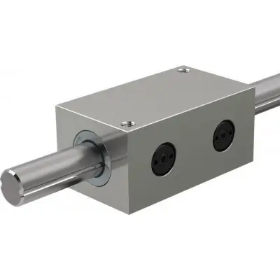
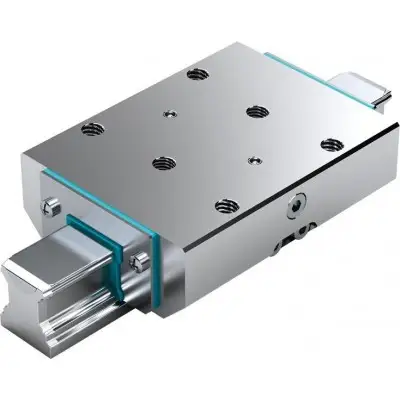
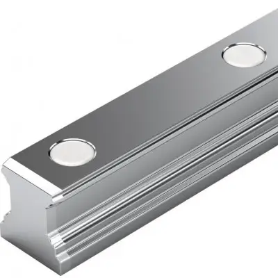
Артикул: rx8294
Бренд: Bosch Rexroth
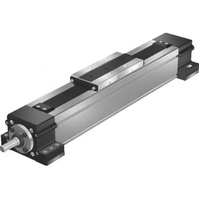
Конструкция. 1) Кронштейн и муфта. 2) Ременная передача. 1 Опора (фиксированный подшипник). 2 Шарико-винтовая передача Rexroth с беззазорной цилиндрической одинарной гайкой. 3 Уплотнительная лента из стали или пластика. 4 Корпус гайки. 5 Крепление ленты. 6 Опорный подшипник (плавающий подшипник). 7 Опора винта (SPU). 8 Защитный профиль крепления двигателя. 9 Кронштейн и муфта. 10 Серводвигатель. 11 Ременная передача. Сборка кронштейна и муфты. Двигатель может быть присоединен ко всем приводным узлам через кронштейн и муфту. Кронштейн крепит двигатель к приводному узлу и служит закрытым корпусом для муфты. Муфта передает крутящий момент двигателя на приводной вал приводного узла без искажающих напряжений. Наши стандартные муфты компенсируют тепловое расширение системы. 1 Двигатель. 2 Кронштейн. 3 Муфта. 4 Приводной узел. Конструкция ременной передачи. Двигатели всех приводных узлов могут быть присоединены с помощью ременной передачи. Это делает общую длину короче, чем при креплении двигателя с кронштейном и муфтой. Компактный закрытый корпус шкива служит защитой для ремня и кронштейном двигателя. Кроме того, доступны различные передаточные отношения (в зависимости от размера):. i = 1. i = 2. Ременная передача может быть установлена в четырех направлениях:. снизу, сверху (RV01 и RV02). слева, справа (RV03 и RV04). 1 Корпус шкива из анодированного алюминиевого профиля. 2 Приводной узел. 3 Зубчатый ремень. 4 Двигатель. 5 Предварительное натяжение зубчатого ремня: приложите усилие предварительного натяга Fpr к двигателю (Fpr указывается при поставке). 6 Крышка. 7 Крепление шкивов с натяжными устройствами. 8 Защитная пластина для ременной передачи.
| Параметр | Значение |
|---|---|
| P мм | 20 |
| Гайки C N | 15480 15210 |
| Фиксированный подшипник N | 17000. |
| P мм | 20 |
| Lc мм | 204. |
| Lmax мм | 3000. |
| P мм | 20 |
| J fix кг·мм² | 16,9 21,7 |
| J вар кг·мм | 0,1004. |
| J m мм² | 0,633 2,533 |
| Nm 0,6 | 0,7 0,8 |
| Nm 0,6 | 0,7 0,8 |
| Nm 0,7 | 0,8 0,9 |
| Nm 0,7 | 0,8 1 |
| AGK-020 MSM041B, MS2N04 | 20 |
| MS2N05 | 20 |
Примечание: См. документ «Расчет» в разделе «Примечания по проектированию». Грузоподъемность и моменты. Типоразмер AGK-020. d0 x x 5 x 10 x x 40. 14400 12600. Общие технические данные. Типоразмер AGK-020. d0 x 20 x 5 20 x 10 20 x 20 20 x 40. Lad с количеством опор винта. 0 мм 86. 1 мм 201. 2 мм 326. 3 мм 451. smin 1) мм 100. mca кг 2,5. кг fix кг 3,5. кг вар кг/мм 062. 1) Минимальный ход для обеспечения надежного распределения смазки. Расчет массы линейной системы перемещения (без крепления двигателя, без двигателя). Расчет длины. Эффективный ход. Данные привода. Типоразмер AGK-020. d0 x 20 x 5 20 x 10 20 x 20 20 x 40. k 40,7 116,7. k k 10,132 40,5285. MRs с количеством опор винта. 0 . 1 1. 2 1,2. 3 1,4. amax м/с² 39,8 50. Примечание: Макс. крутящий момент привода Mp и макс. скорость vmax см. в разделе «Диаграммы / Характеристические кривые». Данные привода для крепления двигателя с помощью ременной передачи. Типоразмер Двигатель d0 x P до L2) Msd1) Jsd MRsd msd F Bt. 20 x 5 1600 6,00 240 0,40 1,24 88 16 AT5. 20 x 10 2000 7,90. 20 x 20 2700 7,94. 20 x 40 3000. 20 x 5 1600 6,00 1420 0,45
Бесплатная доставка по РФ при заказе от 50 000 р.
Компания ООО «Индатэк» работает с юридическими лицами по всей территории России. Каждый день мы осуществляем доставку заказов от Калининграда до Владивостока. Вместе с отгруженным товаром, клиент получает бухгалтерские и гарантийные документы на 12 месяцев. По желанию, вы можете продлить срок гарантии.
При заказе от 50000 руб.
Цены указаны с НДС
И постгарантийное обслуживание