Артикул: rx8371
Бренд: Bosch Rexroth
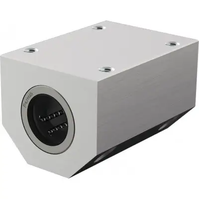
| Параметр | Значение |
|---|---|
| Нормальный радиальный зазор Первичная смазка Dynalub | 510 |
| Технические данные Общие технические данные Ø d мм | 12 16 |
| FR 1) Н | 0,8 1 |
| Усилие страгивания Н | 1,5 2 |
| Радиальный зазор вал h6 мкм + | 32 0 |
| Грузоподъёмность и моменты нагрузки Ød мм | 12 16 |
| C 1) Н | 1310 1700 |
| C0 1) Н | 980 1140 |
| ML0 Нм | 13 18 |
| Номинальная грузоподъёмность рассчитана на общий путь | 100 000 |
| При расчёте на | 50 000 |
| Размеры Размеры Ød мм | 12 16 |
| D мм | 19 24 |
| A мм | 40 45 |
| E1 29 мм ±0,15 | 34 мм |
| E2 35 мм ±0,15 | 40 мм |
| H мм | 17 19 |
| Допуск H 1) мкм + | 24 0 |
| H1 мм | 33 38 |
| H4 мм | 11 13 |
| L мм | 60 65 |
| N1 мм | 16 18 |
| N2 мм | 11 13 |
| S 2) мм | 4,3 5,3 |
| Крепёжные винты ISO | 4762-8.8 |
Облегчённый прецизионный тандемный корпус (алюминий) Две компактные линейные втулки Встроенные уплотнения-скребки 20 25 30 40 50 amax м/с² 150 vmax м/с 5 m кг 0,17 0,24 0,31 0,57 0,8 1,54 2,45 2,5 3 4 1,5 2 3 4,5 6 8 10 + 33 - 1 + 36 0 + 42 - 1 Условия эксплуатации Допустимая температура окружающей среды (мин .. макс) -10 °C .. +80 °C 1) Сопротивление трения, создаваемое линейными втулками со встроенными уплотнениями-скребками с двух сторон при отсутствии радиальной нагрузки. Сопротивление трения зависит от скорости и смазки. 20 25 30 40 50 2290 4760 6250 10360 11660 1800 3900 5580 9300 10700 21 59 103 204 271 1) Номинальная грузоподъёмность указана для главного направления нагрузки. Если направление нагрузки не является главным, значения грузоподъёмности умножаются на следующие коэффициенты: Ø d 12 и 16: f = 0,90, f0 = 0,86, Ø d от 20 до 50: f = 0,79, f0 = 0,68 м. м значения в таблице умножаются на 1,26. Обозначения Символ Описание Единица Ød Диаметры валов мм amax Максимальное ускорение перемещения м/с² C Динамическая грузоподъёмность Н C0 Статическая грузоподъёмность Н FR Сила трения Н m Масса кг ML0 Статическая продольная моментная нагрузка Нм vmax Максимально допустимая скорость м/с² Влияние направления нагрузки на грузоподъёмность Указанные значения грузоподъёмности следует выбирать в зависимости от установки в минимальном или максимальном положении и на основе расчётов. Если направление нагрузки чётко определено и линейные втулки могут быть установлены в максимальном положении, можно использовать значения Cmax (динамическая грузоподъёмность) и C0max (статическая грузоподъёмность). Если ориентированная установка невозможна или направление нагрузки не определено, необходимо использовать минимальные значения грузоподъёмности. Снижение грузоподъёмности при коротком ходе При коротком ходе срок службы валов меньше, чем у линейных втулок. Поэтому указанные значения грузоподъёмности C необходимо умножать на коэффициент f.s. 1) fs = коэффициент 2) s = ход Определение динамической грузоподъёмности 20 25 30 40 50 28 35 40 52 62 53 62 67 87 103 ±0,15 ±0,15 48 мм ±0,15 53 мм ±0,15 69 мм ±0,15 82 мм ±0,15 40 мм ±0,15 45 мм ±0,15 55 мм ±0,15 70 мм ±0,15 85 мм ±0,15 100 мм ±0,15 23 27 30 39 47 + 25 0 + 26 0 + 14 - 12 45 54 60 76 92 15 17 19 24 30 85 105 125 145 22 26 29 38 46 18 22 26 6,6 8,4 10,5 S1 M5 M6 M8 M10 M12 1) Относительно Ø d. 2) Обозначения Символ Описание Единица Ød Диаметры валов мм C/C0 Главное направление нагрузки ML0 Статическая нагрузка крутящего момента Нм Пр
Бесплатная доставка по РФ при заказе от 50 000 р.
Компания ООО «Индатэк» работает с юридическими лицами по всей территории России. Каждый день мы осуществляем доставку заказов от Калининграда до Владивостока. Вместе с отгруженным товаром, клиент получает бухгалтерские и гарантийные документы на 12 месяцев. По желанию, вы можете продлить срок гарантии.

При заказе от 50000 руб.
Цены указаны с НДС
И постгарантийное обслуживание