Артикул: rx8375
Бренд: Bosch Rexroth
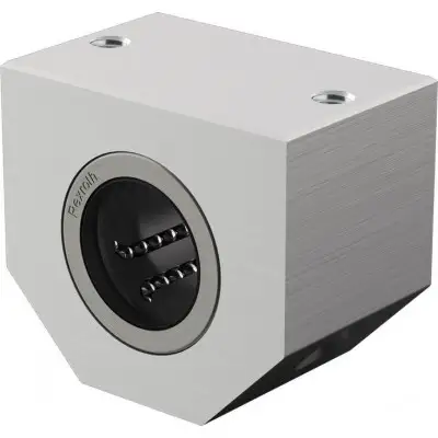
Прецизионный корпус облегчённого типа (алюминий). Линейная втулка eLINE. Встроенные уплотнительные манжеты. Уменьшенный радиальный зазор. Первичная смазка Dynalub 510
| Параметр | Значение |
|---|---|
| FR 1) Н | 0,8 1 |
| Усилие страгивания Н | 1,5 2 |
| Радиальный зазор вала h6 мкм + 8 | 24 |
Общие технические данные. Ø d мм 12 16 20 25 30 40. amax м/с² 150. vmax м/с 5. m кг 0,08 0,11 0,15 0,27 0,4 0,75. 2,5 3. 1,5 2 3 4,5 6 8. + 9 - 25 + 12 - 24 + 18 - 25
Допустимая температура окружающей среды (мин .. макс) -10 °C .. +80 °C. 1) Сопротивление трения, создаваемое линейными втулками с встроенными уплотнительными манжетами с двух сторон при отсутствии радиальной нагрузки. Сопротивление трения зависит от скорости и смазывания. Грузоподъёмности и нагрузочные моменты. Ød мм 12 16 20 25 30 40. C 1) Н 810 1050 1410 2930 3850 6380. C0 1) Н 490 570 900 1950 2790 4650. 1) Грузоподъёмности действительны для основного направления нагружения. Если направление нагрузки не является основным направлением нагружения, грузоподъёмности необходимо умножить на следующие коэффициенты: Ø d 12 и 16: f = 0,90, f0 = 0,86, Ø d от 20 до 50: f = 0,79, f0 = 0,68. Грузоподъёмности основаны на общем пути 100 000 м. При расчёте на 50 000 м значения в таблице необходимо умножить на 1,26.
Символ Описание Единица. Ød Диаметры валов мм. amax Максимальное ускорение перемещения м/с2. C Динамическая грузоподъёмность Н. C0 Статическая грузоподъёмность Н. FR Сила трения Н. m Масса кг. vmax Максимально допустимая скорость м/с. Влияние направления нагрузки на грузоподъёмность. Указанные грузоподъёмности следует выбирать в зависимости от установки в минимальном или максимальном положении и основывать на расчётах. Если направление нагрузки чётко определено и линейные втулки могут быть установлены в максимальном положении, можно использовать грузоподъёмности Cmax. (динамическая грузоподъёмность) и C0 max (статическая грузоподъёмность). Если соосная установка невозможна или направление нагрузки не определено, необходимо использовать минимальные грузоподъёмности. Пониженная грузоподъёмность при коротком ходе. При коротком ходе срок службы валов меньше, чем у линейных втулок. Поэтому указанные в таблицах грузоподъёмности C необходимо умножить на коэффициент f.s. 1) fs = коэффициент 2) s = ход. Определение динамических грузоподъёмностей.
Размеры. Ød мм 12 16 20 25 30 40. D мм 19 24 28 35 40 52. A мм 40 45 53 62 67 87. E 29 мм ±0,15 34 мм ±0,15 40 мм ±0,15 48 мм ±0,15 53 мм ±0,15 69 мм ±0,15. H мм 17 19 23 27 30 39. Допуск на H 1) мкм + 24 0 + 25 0 + 26 0. H1 мм 33 38 45 54 60 76. H4 мм 11 13 15 17 19 24. L мм 28 30 40 50 60. N1 мм 16 18 22 26 29 38. N2 мм 11 13 18 22. S 2) мм 4,3 5,3 6,6 8,4. S1 M5 M6 M8 M10. SW мм 2,5 3 4 5. 1) Относительно Ø d. 2) Крепёжные винты ISO 4762-8.8. Условные обозначения. Символ Описание Единица. Ød Диаметры валов мм. C/C0 Основное направление нагружения.
для проектирования. Расчёт срока службы. Монтаж. Общие указания по монтажу. Ввод в эксплуатацию. Первичная смазка. Линейные втулки поставляются с первичной смазкой. Смазать линейные втулки перед использованием. Данные по сроку службы основаны на первичной смазке и повторно смазанных линейных втулк
Бесплатная доставка по РФ при заказе от 50 000 р.
Компания ООО «Индатэк» работает с юридическими лицами по всей территории России. Каждый день мы осуществляем доставку заказов от Калининграда до Владивостока. Вместе с отгруженным товаром, клиент получает бухгалтерские и гарантийные документы на 12 месяцев. По желанию, вы можете продлить срок гарантии.

При заказе от 50000 руб.
Цены указаны с НДС
И постгарантийное обслуживание