Артикул: rx8392
Бренд: Bosch Rexroth
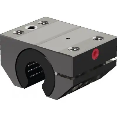
Закалённый и обработанный опорный корпус из подшипниковой стали. Сепаратор шариков из усиленного PA. Шарики из подшипниковой стали. Два стопорных кольца. Полностью уплотнённый (с интегрированными уплотнительными манжетами и продольными уплотнениями)
| Параметр | Значение |
|---|---|
| FR Н | 12 16 |
| Усилие страгивания Н | 24 32 |
Общие технические данные. Ø d мм 30 40 50 60 80. aмакс м/с² 50. vмакс м/с 2. m кг 1.75 3.5 7.1 11.9 29.6. 20 24 30. 40 48 60. μ 1) 01 .. 02. Радиальный зазор Поставляется с валом h5 (нижний предел) и настроен на нулевой зазор
Допустимая температура окружающей среды (мин .. макс) -20 °C .. +100 °C. 1) Коэффициенты трения неуплотнённых радиальных линейных втулок при смазке маслом. Грузоподъёмность и нагрузочные моменты. Ød мм 30 40 50 60 80. C 1) Н 8500 13900 20800 29500 54800. C0 1) Н 9520 16000 24400 34100 61500. 1) Указанная грузоподъёмность действительна для главного направления нагружения ρ = 0°. Значения грузоподъёмности основаны на общем пути 100 000 м. При расчёте на 50 000 м значения в таблице необходимо умножить на 1,26. Обозначения. Символ Описание Единица. Ød Диаметр вала мм. aмакс Максимальное ускорение перемещения м/с². C Динамическая грузоподъёмность Н. C0 Статическая грузоподъёмность Н. FR Сила трения Н. m Масса кг. vмакс Максимально допустимая скорость м/с. Определение динамической грузоподъёмности. Жёсткость. Сочетание радиальной линейной втулки с непрерывно опирающимся направляющим валом обеспечивает точную и жёсткую конструкцию. На следующем рисунке показана зависящая от нагрузки упругая деформация. Диаграмма применима для монтажа:. Без предварительного натяга. С нулевым зазором (без предварительного натяга) для направления нагрузки ρ = 0° – 90° и 270° – 360°. Жёсткость радиальной линейной втулки. Монтаж с предварительным натягом уменьшает упругую деформацию. Дополнительная упругая деформация во всех частях линейной направляющей (корпус, вал, опорная шина вала) зависит от направления нагрузки. Ориентировочные значения общей упругой деформации с элементами R1076 и R1010: коэффициент направления нагрузки, умноженный на упругую деформацию ∂ (из правой диаграммы). 1) F = нагрузка, Н. 2) ∂ = упругая деформация, мм. Общее отклонение в зависимости от направления нагрузки. Направление нагрузки ∂. 0° 90° 180° 270°. Общее отклонение 1 • ∂ 1,8 • ∂ 3,5 • ∂ 1,8 • ∂. Влияние направления нагрузки на грузоподъёмность. Указанные для радиальных линейных втулок значения грузоподъёмности C и C0 действительны для направления нагрузки ρ = 0°. Если внешняя нагрузка действует под углом ρ = 90° – 270°, необходимо учитывать пониженную грузоподъёмность. Динамическая грузоподъёмность в этом случае определяется умножением указанной динамической грузоподъёмности C или C0 на коэффициенты направления нагрузки fρ или fρ0. Этого снижения грузоподъёмности можно избежать путём аккуратного монтажа радиальных линейных втулок. Диаграммы/характеристики. Коэффициенты направления нагрузки.
a) Смазочное отверстие M8x1, закрытое пластиковой заглушкой. b) Радиальный зазор регулируемый. c) Вал с опорной шиной вала, R1012. Размеры. Ød мм 30 40 50 60 80. A мм 100 125 160 190 260. A1 50 мм ±08 62.5 мм ±08 80 мм ±08 95 мм ±08 130 мм ±08. A2 мм 68 85 105 130 170. E1 мм 76 94 122 150 205. E2 мм 40 50 65 75 100. H 1) 32 мм ±08 40 мм ±08 50 мм ±08 60 мм ±08 80 мм ±08. H1 мм 53 66 81.5 97 130. H2 мм 65 80 100 120 160. L мм 75 100 1
Бесплатная доставка по РФ при заказе от 50 000 р.
Компания ООО «Индатэк» работает с юридическими лицами по всей территории России. Каждый день мы осуществляем доставку заказов от Калининграда до Владивостока. Вместе с отгруженным товаром, клиент получает бухгалтерские и гарантийные документы на 12 месяцев. По желанию, вы можете продлить срок гарантии.
При заказе от 50000 руб.
Цены указаны с НДС
И постгарантийное обслуживание