Артикул: rx8412
Бренд: Bosch Rexroth
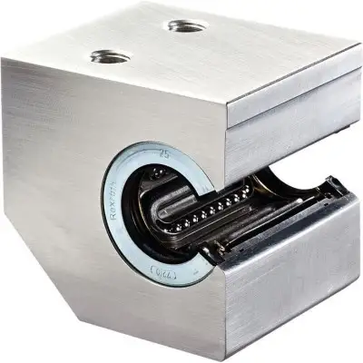
Облегчённый прецизионный корпус (алюминий). Стандартная линейная втулка. Фиксация коническим штифтом с канавкой. Наружные уплотнения. Без маслёнки
Линейные комплекты со стандартными линейными втулками с боковым раскрытием. Если нагрузка прикладывается против направления раскрытия открытых линейных втулок, это приведёт к снижению грузоподъёмности. Для предотвращения этого и облегчения установки специальных линейных втулок были разработаны линейные комплекты с боковым раскрытием.
| Параметр | Значение |
|---|---|
| FR 1) Н | 6 7 |
| Усилие страгивания Н | 16 19 |
| Радиальный зазор вала h6 2) мкм + | 36 |
Общие технические данные. Ø d мм 20 25 30 40 50. amax м/с² 100 50. vmax м/с 2.5 2. m кг 0.45 0.85 1.3 2.3 3.7. 8 11 14. 24 32 40. + 4 + 38 + 4 + 45 + 5
Допустимая температура окружающей среды (мин .. макс) -10 °C .. +80 °C. 1) Силы трения, создаваемые линейными втулками со встроенными уплотнительными скребками с двух сторон при отсутствии радиальной нагрузки. Силы трения зависят от скорости и смазки. 2) Зажато (закреплено). Грузоподъёмность и моменты нагрузки. Ød мм 20 25 30 40 50. C 1) Н 1280 2270 2890 5280 8470. C0 1) Н 970 1750 2390 4000 6900. 1) Номинальная грузоподъёмность действительна для основного направления нагрузки. Номинальная грузоподъёмность рассчитана на общий путь 100 000 м. При расчёте на 50 000 м значения в таблице необходимо умножить на 1.26. Обозначения. Символ Описание Ед. изм. Ød Диаметры валов мм. amax Максимальное ускорение перемещения м/с². C Динамическая грузоподъёмность Н. C0 Статическая грузоподъёмность Н. FR Сила трения Н. m Масса кг. vmax Максимально допустимая скорость м/с. Для нагрузки в направлении раскрытия см. диаграммы нагрузки (раздел «Диаграммы»). Влияние направления нагрузки на грузоподъёмность открытых линейных втулок. Номинальная грузоподъёмность C и C0 действительна для основного направления нагрузки ρ = 0°. Для всех других направлений нагрузки номинальную грузоподъёмность необходимо умножить на коэффициенты fρ (динамическая грузоподъёмность C) или fρ0 (статическая грузоподъёмность C0). Установка специальных линейных втулок позволяет предотвратить снижение грузоподъёмности (см. Линейный комплект с боковым раскрытием). Определение динамической грузоподъёмности.
Размеры. Ød мм 20 25 30 40 50. D мм 32 40 47 62 75. A мм 60 75 86 110 127. E1 22 мм ±0.15 28 мм ±0.15 34 мм ±0.15 43 мм ±0.15 50 мм ±0.15. E2 30 мм ±0.15 36 мм ±0.15 42 мм ±0.15 48 мм ±0.15 62 мм ±0.15. E3 мм 33 42 48 62 70. E4 мм 42 52 60 68 85. H мм 30 35 40 45 50. Допуск H 1) мкм + 5 - 19 + 4 - 21. H1 мм 60 72 82 100 115. H4 мм 22 26 30 38 45. L мм 54 67 79 91 113. M 1) 17 мм ±0.01 21 мм ±0.01 25 мм ±0.01 32 мм ±0.01 38 мм ±0.01. N1 мм 42 50 55 67 78. N2 мм 15 18 24 30. S 2) мм 8.4 10.5 13.5 15.5 17.5. S1 M10 M12 M16 M20. S2 3) мм 6 8 10 12. SW мм 2.5 3 4 5. V мм 5 6.5 8 10 12. W 4) мм 10 12.5 16.8 21. 1) Зажато (закреплено) относительно Ø d. 2) Цилиндрические болты ISO 4762-8.8. 3) Центрирование штифтовым отверстием. 4) Минимальный размер относительно Ø d. Обозначения. Символ Описание Ед. изм. Ød Диаметры валов мм. C/C0 Основное направление нагрузки.
для проектирования. Расчёт срока службы. Монтаж. См. указания по установке линейных комплектов с боковым раскр
Бесплатная доставка по РФ при заказе от 50 000 р.
Компания ООО «Индатэк» работает с юридическими лицами по всей территории России. Каждый день мы осуществляем доставку заказов от Калининграда до Владивостока. Вместе с отгруженным товаром, клиент получает бухгалтерские и гарантийные документы на 12 месяцев. По желанию, вы можете продлить срок гарантии.
При заказе от 50000 руб.
Цены указаны с НДС
И постгарантийное обслуживание