Артикул: rx8416
Бренд: Bosch Rexroth
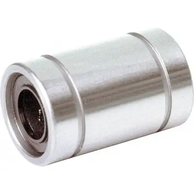
Прочная цельнометаллическая конструкция со стальным сепаратором шариков для тяжёлых условий эксплуатации и сильного загрязнения. Множество карманов, служащих резервуарами для смазки, для увеличенных интервалов смазки или смазки на весь срок службы. Дополнительные встроенные уплотнительные скребки. Нержавеющая сталь для медицинской, химической и пищевой промышленности. Закрытого типа, для самонесущих валов
| Параметр | Значение |
|---|---|
| Шарики из нержавеющей стали, аналог | 1.4125. |
| Сепаратор шариков из нержавеющей стали, аналог | 1.4301. |
| Встроенные стопорные кольца из нержавеющей стали, аналог | 1.4006, |
Для применения в деревообработке, литейном производстве, цементных заводах. Карманы собирают любую грязь, которая могла проникнуть внутрь, предотвращая заклинивание линейной втулки. Закалённая и обработанная наружная втулка из нержавеющей стали, аналог 1.4125. или уплотнительные скребки
| Параметр | Значение |
|---|---|
| FR Н | 0.4 1 |
| Усилие страгивания Н | 0.8 1 |
| Ряды шариков | 4 5 |
| Допуск рабочего диаметра отверстия мкм + | 8 0 |
| Радиальный зазор вала h6 4) мкм + | 12 |
Общие технические данные. Ø d мм 3 8 10 16 20 25 30 40. amax м/с² 100. vmax м/с 2.5. m кг 01 02 0.011 0.022 0.036 0.045 0.06 0.1 0.235 0.36 0.77. ) 2) 0.5 1) 2) 1 1) 2) 2 1) 2) 3 1) 2) 4 1) 2) 5 1) 2) 6 1) 2) 8 1) 2). ) 1 1) 2 1) 6 1) 9 1) 12 1) 14 1) 18 1) 24 1). μ 3) 0,001 .. 0,004. 4 5 6. + 11 + 1 + 12 + 2 + 8 0 + 12 + 2 + 14 + 2 + 16 + 2 + 19 + 2. 12 + 2 + 14 + 2 + 16 + 4 + 18 + 5 + 20 + 5 + 22 + 5 + 23 + 6 + 25 + 6 + 30 + 7
Допустимая температура окружающей среды (мин .. макс) 5) -10 °C .. +80 °C. 1) Один уплотнительный скребок: Умножить на коэффициент 0.5. 2) Силы трения, создаваемые линейными втулками со встроенными уплотнительными скребками с двух сторон при отсутствии радиальной нагрузки. Силы трения зависят от скорости и смазки. 3) Коэффициенты трения неуплотнённых линейных втулок при смазке маслом. Коэффициент трения минимален при большой нагрузке, но может быть выше указанного значения даже при малой нагрузке. 4) Определено на основе статистики рабочего диаметра отверстия и допусков вала. Рекомендуемый допуск отверстия корпуса: H6 или H7. 5) Только неуплотнённые линейные втулки со стальными сепараторами шариков могут использоваться при повышенных температурах. Учитывайте снижение грузоподъёмности. Грузоподъёмность и моменты нагрузки. Ød мм 3 4 5 8 10 12 16 20 25 30 40. Cmin Н 55 70 160 210 300 400 460 680 780 1250 1720. Cmax Н 65 80 185 240 350 460 530 800 830 1320 1820. C0min Н 45 60 180 235 260 420 440 860 1620 2000 3300. C0max Н 65 85 250 330 370 600 630 1250 2100 2500 4200. Номинальная грузоподъёмность рассчитана на общий путь 100 000 м. При расчёте на 50 000 м значения в таблице необходимо умножить на 1.26. Обозначения. Символ Описание Ед. изм. Ød Диаметры валов мм. amax Максимальное ускорение перемещения м/с². Cmax Максимальная динамическая грузоподъёмность Н. Cmin Минимальная динамическая грузоподъёмность Н. C0max Максимальная статическая грузоподъёмность Н. C0min Минимальная статическая грузоподъёмность Н. FR Сила трения Н. m Масса кг. vmax Максимально допустимая скорость м/с. μ Коэффициент трения. Влияние направления нагрузки на грузоподъёмность закрытых линейных втулок. Указанные значения грузоподъёмности следует выбирать в зависимости от установки в минимальном или макси
Бесплатная доставка по РФ при заказе от 50 000 р.
Компания ООО «Индатэк» работает с юридическими лицами по всей территории России. Каждый день мы осуществляем доставку заказов от Калининграда до Владивостока. Вместе с отгруженным товаром, клиент получает бухгалтерские и гарантийные документы на 12 месяцев. По желанию, вы можете продлить срок гарантии.
При заказе от 50000 руб.
Цены указаны с НДС
И постгарантийное обслуживание