Артикул: rx8463
Бренд: Bosch Rexroth
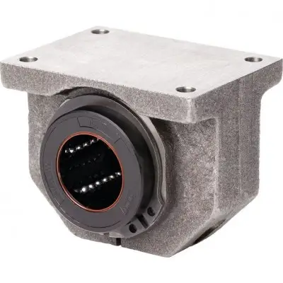
Прецизионный корпус (чугун/сталь с пластинчатым графитом) Шариковая втулка Super B без функции самовыравнивания Встроенные грязесъемные уплотнения Описание продукта Для направляющих с нулевым зазором или с предварительным натягом. Регулировочный винт для регулировки радиального зазора. Эти линейные наборы поставляются с нулевым зазором
| Параметр | Значение |
|---|---|
| Общие технические данные Ø d мм | 12 16 |
| FR 2) Н | 0,8 1 |
| Усилие отрыва Н | 1,5 2 |
| C 1) Возможна скорость до | 5 м |
| Испытания показали общий ход от | 50 |
| Грузоподъемность и грузовой момент Ød мм | 12 16 |
| C 1) Н | 1020 1500 |
| C0 1) Н | 490 830 |
| Номинальная нагрузка основана на общем пробеге | 100, 00 |
| При расчете на | 50 000 |
| Размеры Размеры Ød мм | 12 16 |
| D мм | 22 26 |
| A 1) мм | 42 50 |
| A1 1) мм | 21 26 |
| B мм | 32 1 |
| B1 мм | 20 22 |
| E1 32 мм ±0,15 | 40 мм |
| E2 23 мм ±0,15 | 26 мм |
| H мм | 18 22 |
20 25 30 40 amax м/с² 150 vmax 1) м/с 3 м кг 0,15 0,24 0,41 0,79 1,19 2,26 3,15 2,5 3 4 1,5 2 3 4,5 6 8 10 Радиальный зазор Крепится к валу h5 (нижний предел) и устанавливается на нулевой зазор Условия эксплуатации Допустимая температура окружающей среды (мин .. макс) -10 °C .. +80 ° /с. Срок службы ограничен повышенным износом пластиковых деталей. 50 • 105 м до 100 • 105 м без сбоев. 2) Фрикционное сопротивление, создаваемое шариковыми втулками со встроенными грязесъемными уплотнениями с двух сторон, когда они не подвергаются радиальной нагрузке. Сопротивление трения зависит от скорости и смазки. 20 25 30 40 50 2470 5040 5860 10070 14730 1340 2470 3570 5570 8280 1) Нагрузка Номинальные значения действительны для основного направления нагрузки. Если направление нагрузки не является основным направлением нагрузки, номинальную динамическую нагрузку необходимо умножить на следующие коэффициенты: Ø d 12 и 16: f = 0,82, f0 = 0,86, Ø d 20–50: f = 0,82, f0 = 0,78. м. м значения в таблице необходимо умножить на 1,26. Обозначение Символ Описание Единица измерения Ød Диаметры вала мм amax Максимальный ход ускорения м/с2 C Допустимая динамическая нагрузка Н C0 Допустимая статическая нагрузка Н FR Сила трения Н м Масса кг vмакс Максимально допустимая скорость м/с Влияние направления нагрузки на номинальную нагрузку закрытых шариковых втулок Перечисленные значения грузоподъемности следует выбирать в зависимости от установки в минимальном или максимальном положении и основываться на расчетах. Если направление нагрузки четко определено и шариковые втулки можно установить в максимальном положении, допустимая нагрузка Cmax. (номинальная динамическая нагрузка) и C0 max (номинальная статическая нагрузка). Если выровненная установка невозможна или направление нагрузки не определено, необходимо использовать минимальные значения грузоподъемности. Пониженная грузоподъемность при коротком ходе. В случае короткого хода срок службы вала меньше, чем у шариковой втулки «Супер». Поэтому значения грузоподъемности C, указанные в таблицах, необходимо умножить на коэффициент f.s. 1) fs = коэффициент 2) s = путь движения Определение номинальной динамической нагрузки 20 25 30 40 50 32 40 47 62 75 60 74 84 108 130 28 38 41 51 57 ) 35 1) 42 1) 54 1) 60 1) 78 1) 70 1) 28 40 48 56 72 ±0,15 45 мм ±0,15 60 мм ±0,15 68 мм ±0,2 86 мм ±0,2 108 мм ±0,2 ±0,15 32 мм ±0,15 40 мм ±0,15 45 мм ±0,2 58 мм ±0,2 50 мм ±0,2 25 30 35 45 50 Допуск для H
Бесплатная доставка по РФ при заказе от 50 000 р.
Компания ООО «Индатэк» работает с юридическими лицами по всей территории России. Каждый день мы осуществляем доставку заказов от Калининграда до Владивостока. Вместе с отгруженным товаром, клиент получает бухгалтерские и гарантийные документы на 12 месяцев. По желанию, вы можете продлить срок гарантии.

При заказе от 50000 руб.
Цены указаны с НДС
И постгарантийное обслуживание