Артикул: rx8478
Бренд: Bosch Rexroth
| Параметр | Значение |
|---|---|
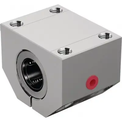
| Суперлинейная втулка H Компенсирует перекосы до | 30 |
| Технические данные Общие технические данные Ø d мм | 20 25 |
| FR 1) Н | 2,5 3 |
| Усилие страгивания Н | 5 7 |
| Нагрузочная способность и нагрузочные моменты Ød мм | 20 25 |
| C 1) Н | 2520 4430 |
| C0 1) Н | 1880 3360 |
| Номинальные нагрузки основаны на общем пути перемещения | 100 000 |
| При расчёте на | 50 000 |
Прецизионный корпус (алюминий) ' Встроенные уплотнительные манжеты Крепление болтом Особенности Возможность повторного смазывания 30 40 50 60 amax м/с² 150 vmax м/с 5 m кг 0,29 0,58 0,88 1,63 2,7 5,2 4 5 6 7 9 12 15 18 Радиальный зазор Зажато на валу h5 (нижний предел) и установлено с нулевым зазором Условия эксплуатации Допустимая температура окружающей среды (мин .. макс) -20 °C .. +80 °C 1) Сопротивление трения, создаваемое линейными втулками с интегрированными уплотнительными манжетами с двух сторон при отсутствии радиальной нагрузки. Сопротивление трения зависит от скорости и смазки. 30 40 50 60 6300 9680 16000 23500 5230 7600 12200 18700 1) Номинальные нагрузки применимы для основного направления нагружения. м. м значения в таблице необходимо умножить на 1,26
Символ Описание Единица Ød Диаметр вала мм amax Максимальное ускорение перемещения м/с² C Динамическая нагрузочная способность Н C0 Статическая нагрузочная способность Н FR Сила трения Н m Масса кг vmax Максимально допустимая скорость м/с См. «Технические данные – Коэффициенты направления нагрузки» и раздел диаграмм/характеристических кривых для точных значений по 4 основным направлениям нагружения. Влияние направления нагрузки на номинальную нагрузку a) Закрытая b) Открытая Основное направление нагрузки Коэффициенты направления нагрузки Номинальные нагрузки C и C0 применимы для направления нагрузки ρ = 0°. Для всех других направлений нагрузки номинальные нагрузки необходимо умножать на коэффициенты fr (динамическая нагрузка C) или fρ0 (статическая нагрузка C0). Коэффициент направления нагрузки Super H Вал Коэффициент направления нагрузки (динамическая нагрузочная способность) Ø d (мм) ⇩ ⇒⇐ ⇑ ⇩ ⇒⇐ ⇑ 20 - 25 1 0,80 0,98 1 0,80 0,67 30 - 60 1 0,70 0,91 1 0,70 0,62 Коэффициент направления нагрузки (статическая нагрузочная способность) 20 - 25 1 0,70 0,87 1 0,70 0,67 30 - 60 1 0,62 0,80 1 0,62 0,61 Снижение нагрузочной способности при коротком ходе При коротком ходе срок службы вала меньше, чем у суперлинейной втулки. Поэтому номинальные нагрузки C, указанные в таблицах, необходимо умножить на коэффициент f.s. 1) fs = коэффициент 2) s = путь перемещения Определение динамической нагрузочной способности
Бесплатная доставка по РФ при заказе от 50 000 р.
Компания ООО «Индатэк» работает с юридическими лицами по всей территории России. Каждый день мы осуществляем доставку заказов от Калининграда до Владивостока. Вместе с отгруженным товаром, клиент получает бухгалтерские и гарантийные документы на 12 месяцев. По желанию, вы можете продлить срок гарантии.

При заказе от 50000 руб.
Цены указаны с НДС
И постгарантийное обслуживание