Артикул: rx8484
Бренд: Bosch Rexroth
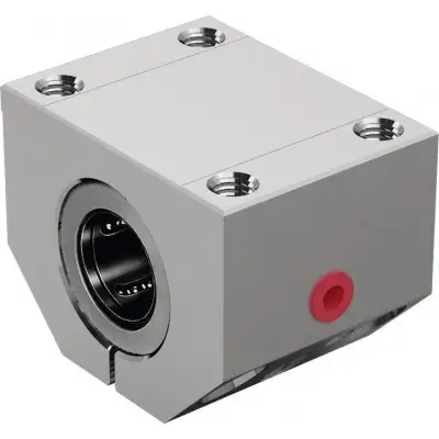
Легкий прецизионный корпус (алюминий). Супер-линейные втулки SH. Компенсируют несоосность до 30'. Встроенные скребковые уплотнения. Крепление болтом
С возможностью повторной смазки.
| Параметр | Значение |
|---|---|
| FR 1) Н | 2,5 3 |
| Усилие страгивания Н | 5 7 |
Общие технические данные. Ø d мм 20 25 30 40 50. amax м/с² 150. vmax м/с 5. m кг 0,31 0,63 0,97 1,86 3,1. 4 5 6. 9 12 15. Радиальный зазор Зажато на валу h5 (нижний предел) с установкой нулевого зазора
Допустимая температура окружающей среды (мин .. макс) -20 °C .. +80 °C. 1) Силы трения, создаваемые линейными втулками со встроенными скребковыми уплотнениями с двух сторон при отсутствии радиальной нагрузки. Силы трения зависят от скорости и смазки. Грузоподъемность и моменты нагрузки. Ød мм 20 25 30 40 50. C 1) Н 3530 6190 8800 13500 22300. C0 1) Н 2530 4530 7180 10400 16800. 1) Номинальная грузоподъемность указана для основного направления нагрузки. Значения основаны на общем пути 100 000 м. При расчете на 50 000 м табличные значения следует умножить на 1,26.
Символ Описание Единица. Ød Диаметры вала мм. amax Максимальное ускорение перемещения м/с². C Динамическая грузоподъемность Н. C0 Статическая грузоподъемность Н. FR Сила трения Н. m Масса кг. vmax Максимально допустимая скорость м/с. См. раздел «Технические данные – Коэффициенты направления нагрузки» и раздел диаграмм/характеристических кривых для точных значений по 4 основным направлениям нагрузки. Влияние направления нагрузки на грузоподъемность. a) Закрытая b) Открытая. Основное направление нагрузки. Коэффициенты направления нагрузки. Номинальная грузоподъемность C и C0 указана для направления нагрузки ρ = 0°. Для всех остальных направлений нагрузки значения грузоподъемности должны быть умножены на коэффициенты fr (динамическая грузоподъемность C) или fρ0 (статическая грузоподъемность C0). Коэффициент направления нагрузки Super SH Вал. Коэффициент направления нагрузки (динамическая грузоподъемность). Ø d (мм) ⇩ ⇒⇐ ⇑ ⇩ ⇒⇐ ⇑. 20 - 25 1 0,79 1 1 0,79 0,52. 30 - 60 1 0,86 1 1 0,86 0,59. Коэффициент направления нагрузки (статическая грузоподъемность). 20 - 25 1 0,68 1 1 0,68 0,50. 30 - 60 1 0,83 1 1 0,83 0,55. Снижение грузоподъемности при коротком ходе. При коротком ходе срок службы вала меньше, чем у супер-линейной втулки. Указанная в таблицах динамическая грузоподъемность C должна быть умножена на коэффициент f.s. 1) fs = коэффициент 2) s = путь перемещения. Снижение грузоподъемности при высокой нагрузке. Грузоподъемность снижается при высокой нагрузке F. Динамическая грузоподъемность должна быть умножена на коэффициент нагрузки f.F. 1) fF = коэффициент нагрузки. Определение динамической грузоподъемности. Диаграммы/характеристические кривые. Коэффициенты направления нагрузки. a) Закрытая b) Открытая. Супер-линейные втулки могут устанавливаться в любом положении. Выберите положение, обеспечивающее, чтобы основное направление нагрузки всегда было ρ = 0°.
a) Смазочное отверстие, закрытое пластиковой заглушкой. Размеры. Ød мм 20 25 30 40 50. D мм 32 40 47 62 75. A мм 60 78 87 108 132. E1 45 мм ±0,15 60 мм ±0,15 68 мм ±0,15 86 мм ±0,15 108 мм ±0,2. E2 32 мм ±0,15 40 мм ±0,15 45 мм ±0,15 58 мм ±0,15 50 мм ±0,2. E3 мм 50 64 72 90 108. E4 мм 15 17 20 25 85. H мм 25 30 35 45 50. Допуск для H 1) мкм + 8 - 16. H1 мм 50 60 70 90 [ОПИСАНИЕ УСЕЧЕНО — 3000 символов]
Бесплатная доставка по РФ при заказе от 50 000 р.
Компания ООО «Индатэк» работает с юридическими лицами по всей территории России. Каждый день мы осуществляем доставку заказов от Калининграда до Владивостока. Вместе с отгруженным товаром, клиент получает бухгалтерские и гарантийные документы на 12 месяцев. По желанию, вы можете продлить срок гарантии.
При заказе от 50000 руб.
Цены указаны с НДС
И постгарантийное обслуживание