Артикул: rx8740
Бренд: Bosch Rexroth

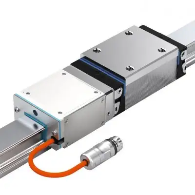
Кулачковые роликовые направляющие Rexroth были специально разработаны для подъемно-транспортной техники и автоматизации. Обзор изделия Технические данные Технические данные Типоразмер 20 Fy макс Н 350 F0y макс Н 350 Fz макс Н 200 F0z макс Н 300 Mx макс Нм 1,4 M0x макс Нм 2,2 My макс Нм 3,4 M0y макс Нм 5,1 Mz макс Нм 6,1 M0z макс Нм 6,1 vмакс 1) м/с 10 aмакс м/с² 50 Термостойкость -20 °C .. +80 °C Масса кг 0.08 1) Для средней нагрузки. Внимание: Не использовать для расчета ожидаемого срока службы! Для расчета срока службы используйте значения грузоподъемности и моментов, приведенные в таблицах для расчета срока службы. Грузоподъемность и моменты для расчета срока службы Типоразмер 20 Cy Н 1150 C0y Н 800 Cz Н 668 C0z Н 392 MX Нм 4,8 M0x Нм 2,8 My Нм 11,3 M0y Нм 6,6 Mz Нм 19,5 M0z Нм 13,5 Соблюдайте максимально допустимые нагрузки по усилиям и моментам, указанные в таблице «Технические данные»! Условные обозначения Символ Описание Ед.изм. Рисунок Cy Динамическая грузоподъемность в направлении y Н C0y Статическая грузоподъемность в направлении y Н Cz Динамическая грузоподъемность в направлении z Н C0z Статическая грузоподъемность в направлении z Н Fy макс Максимальная динамическая нагрузка в направлении y Н F0y макс Максимальная статическая нагрузка от результирующей силы в направлении y Н Fz макс Максимальная динамическая нагрузка в направлении z Н F0z макс Максимальная статическая нагрузка от результирующей силы в направлении z Н Mx макс Максимально допустимый динамический крутящий момент относительно оси x Нм M0x макс Максимально допустимый статический крутящий момент относительно оси x Нм My макс Максимально допустимый динамический крутящий момент относительно оси y Нм M0y макс Максимально допустимый статический крутящий момент относительно оси y Нм Mz макс Максимально допустимый динамический крутящий момент относительно оси z Нм M0z макс Максимально допустимый статический крутящий момент относительно оси z Нм vмакс Максимально допустимая скорость м/с aмакс Максимальное ускорение перемещения м/с2 MX Динамический крутящий момент относительно оси x Нм M0x Статический крутящий момент относительно оси x Нм My Динамический крутящий момент относительно оси y Нм M0y Статический крутящий момент относительно оси y Нм Mz Динамический крутящий момент относительно оси z Нм M0z Статический крутящий момент относительно оси z Нм Жесткость Повышенная жесткость может быть достигнута при более высоком усилии предварительного натяга с помощью эксцентриковой регулировки. Ускорение Допускаются высокие ускорения при условии отсутствия проскальзывания. Для этого усилие предварительного натяга FV увеличивается эксцентриковой регулировкой; см. диаграмму. Внимание: Максимально допустимая нагрузка снижается при увеличении усилия предварительного натяга. 1) Допустимый диапазон 2) a = ускорение 3) Fv/Cy = стандартная настройка Размеры 1) Эксцентриковая регулировка Размеры Типоразмер 20 A мм 28 A1 мм 33 B мм 66 B1 мм 56 E1 мм 20 E2 мм 33 E3 мм 3 E4 мм 34 E5 M5 H мм 28 H1 мм 8.5 H2 мм 13 H3 мм 20 SW1 мм 2 SW2 мм 7 Информация для проектирования Срок службы и коэффициент запаса по нагрузке Монтаж Указания по монтажу Техническое обслуживание Смазка Примечания по поставке Центрирующие штифты уже затянуты при поставке.
Номера материалов Типоразмер Номер детали Данные САПР Купить 20 R190511900 Загрузки Профильн
Бесплатная доставка по РФ при заказе от 50 000 р.
Компания ООО «Индатэк» работает с юридическими лицами по всей территории России. Каждый день мы осуществляем доставку заказов от Калининграда до Владивостока. Вместе с отгруженным товаром, клиент получает бухгалтерские и гарантийные документы на 12 месяцев. По желанию, вы можете продлить срок гарантии.
При заказе от 50000 руб.
Цены указаны с НДС
И постгарантийное обслуживание