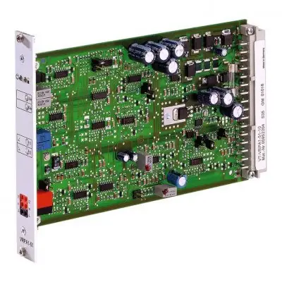
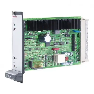
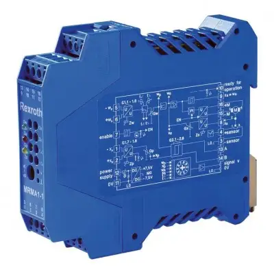
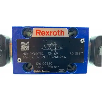
Характеристики
Комплектация 1X Аналоговый, формат Еврокарта Для клапанов: FES 50 и FES 63 (начиная с комплектации 3X)
Особенности
- Дифференциальный вход, переключаемый с входа по напряжению на вход по току Два неизолированных входа задающего сигнала Вход разрешения и вход "отключения разгона" Амплитуда, нулевая точка и регулируемое время разгона Защита от переполюсовки рабочего напряжения Выходы задающего сигнала и фактического значения Светодиодная индикация "готовность к работе" Описание продукта Примечание: Предустановка задающего сигнала 0 В не означает "дроссель в седельном положении". При фактическом значении 0 В золотник дросселя находится в положительном перекрытии
- Задающий сигнал 0 В дает фактическое значение 0 В. В зависимости от перепада давления утечка масла все еще присутствует
- Если сигнал разрешения не подан или выходной каскад заблокирован из-за неисправности, золотник дросселя падает в седло и обеспечивает герметичное уплотнение
- В седельном положении измеримое фактическое значение > +0,5 В (зависит от типа клапана). При использовании внешнего потенциометра времени внутренние потенциометры времени разгона должны быть установлены на максимум (напряжения на измерительных гнездах "t1" и "t2" прибл. 20 мВ). Максимальное время разгона уменьшается, так как значение сопротивления внешнего потенциометра включается параллельно внутреннему потенциометру (прибл. 500 кОм). В этом случае время разгона для нарастания и спада нельзя установить раздельно
- При подаче напряжения >10 В на переключающий вход "Отключение разгона" или установке перемычки X4 время разгона устанавливается на минимальное значение (прибл. 15 мс). Переключающий вход тогда неэффективен
- Минимальное значение действительно для обоих направлений
- Расчет времени разгона Перемычка X9 установлена (время разгона "короткое") Перемычка X8 установлена (время разгона "длинное") Действительно: U = Напряжение в вольтах на измерительном гнезде "t1" или "t2" t = Время разгона в секундах для нарастания и спада Функция разгона Последующий генератор разгона [3] формирует линейно нарастающий выходной сигнал из заданного ступенчатого входного сигнала
- Постоянные времени выходного сигнала (время разгона) регулируются потенциометрами "t1" (нарастание) и "t2" (спад), доступными через переднюю панель
- Указанное максимальное время разгона относится к ступени задающего сигнала 100 % и может составлять прибл. 5 с или 50 с в зависимости от настройки перемычек (X8, X9). Если на вход генератора разгона [3] подается ступень задающего сигнала менее 100 %, время разгона будет соответственно короче
- Текущее время разгона можно проверить на измерительных гнездах "t1" (нарастание) и "t2" (спад). Подробную информацию см. в разделе Технические данные
- Блок питания После подачи рабочего напряжения внутренний блок питания [6] создает напряжение ±9 В относительно измерительного нуля (M0). Относительно нагрузочного нуля (L0) оно повышено на +9 В. Напряжения +9 В и –9 В (–9 В соответствует L0) подаются на клеммную колодку X1 и могут использоваться внешне (например, для потенциометра задающего сигнала)
Бесплатная доставка по РФ при заказе от 50 000 р.
Компания ООО «Индатэк» работает с юридическими лицами по всей территории России. Каждый день мы осуществляем доставку заказов от Калининграда до Владивостока. Вместе с отгруженным товаром, клиент получает бухгалтерские и гарантийные документы на 12 месяцев. По желанию, вы можете продлить срок гарантии.