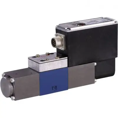
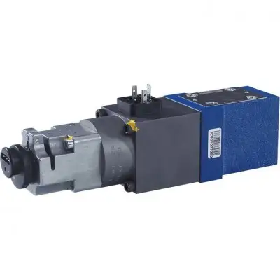
Артикул: rx7320
Бренд: Bosch Rexroth
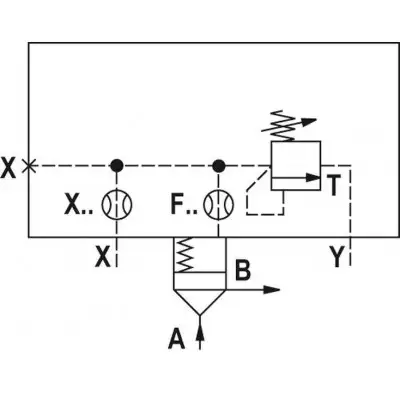
01 02 03 04 05 06 07 08 09 10 11 12 LFA DB - / 450 P Тип 01 Управляющая крышка LFA LFA Типоразмер 02 NG 16 16 NG 25 25 NG 32 32 NG 40 40 NG 50 50 NG 63 63 NG 80 80 NG 100 100 Исполнение 03 Управляющая крышка "DB" с ручной регулировкой давления DB Типы регулировки предохранительных клапанов 04 Поворотная рукоятка 1 Шестигранник с защитным колпачком / внутренний шестигранник 2 Серия компонентов 05 Серия компонентов 70 … 79 (70 … 79: неизменные установочные и монтажные размеры) 1) 7X Серия компонентов 60 … 69 (60 … 69: неизменные установочные и присоединительные размеры) 2) 6X Серия 06 Серия высокого давления 450 Регулировка предохранительных клапанов 07 Номинальное давление не установлено без кода Предохранительный клапан установлен на номинальное давление - Установлен предохранительный клапан с типовым испытанием согласно Директиве по оборудованию под давлением 2014/68/EU E Предохранительный клапан установлен на номинальное давление и опломбирован P Давление настройки / давление срабатывания (информация не применима к исполнению "без кода" в пункте 07) 08 410 бар 410 420 бар 420 430 бар 430 440 бар 440 430 бар 450 Материал уплотнений 09 H-ECOPUR P Соблюдать совместимость уплотнений с используемой рабочей жидкостью. (Другие уплотнения по запросу) Монтаж дросселя 10 Дроссель в канале X 3) X. 11 Дроссель в канале F 3) F. 12 Дроссель в канале D 3) D. 1) Серия компонентов 7X для типоразмеров 16…63 2) Серия компонентов 6X для типоразмеров 80 и 100 3) Данный дроссель выполнен как резьбовой дроссель. Если дроссель должен быть установлен, соответствующая буква кода с диаметром дросселя в 1/10 мм должна быть указана в обозначении типа. Пример: D10 = Дроссель с диаметром 1,0 мм в канале D. Для других диаметров дросселей см. диаграммы/характеристики. Типоразмер Дроссель в канале X F D 16 X08 F10 - 25 X08 F10 - 32 - F12 D08 40 - F12 D10 50 - F15 D20 63 - F20 D25 80 - F25 D25 100 - F25 D30 1) Данный дроссель выполнен как резьбовой дроссель. Если
Бесплатная доставка по РФ при заказе от 50 000 р.
Компания ООО «Индатэк» работает с юридическими лицами по всей территории России. Каждый день мы осуществляем доставку заказов от Калининграда до Владивостока. Вместе с отгруженным товаром, клиент получает бухгалтерские и гарантийные документы на 12 месяцев. По желанию, вы можете продлить срок гарантии.
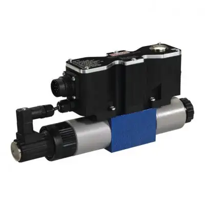
При заказе от 50000 руб.
Цены указаны с НДС
И постгарантийное обслуживание