Артикул: rx8116
Бренд: Bosch Rexroth
| Параметр | Значение |
|---|---|
| Крутящий момент Продольный момент Продольный момент | 1 1 |
| Fz Fy Mx My Mz | 2 1 |
| Fz Fy Mx ‒ ‒ | 3 2 |
| Fz Fy ‒ My Mz | 4 2 |
| Fz Fy ‒ ‒ ‒ | 5 2 |
| Fz Fy ‒ ‒ ‒ | 6 2 |
| Fz Fy ‒ ‒ ‒ Нагрузки и моменты Типоразмер | 20 25 |
| C1 C2 C3 C1 C2 C3 C1 C2 C3 C1 C2 C3 C1 C2 C3 Масса, кг | 0.67 0.91 |
| Fy max Н | 9400 11400 |
| MZ max Нм | 42 53 |
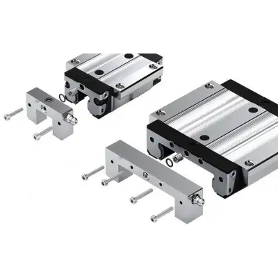
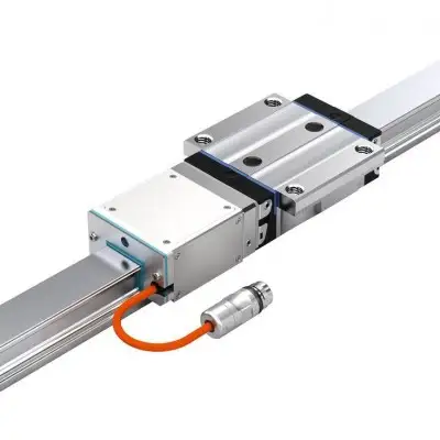
Область применения: Для высоких требований к жёсткости Описание продукта Описание продукта Технические данные Общие технические данные и расчёты направляющих кареток Нагрузки от сил и моментов на направляющую каретку Силы, действующие на систему, распределяются между направляющими каретками в зависимости от схемы установки. Нагрузки от сил и моментов, возникающие в результате действующих сил, необходимо рассчитывать для каждой направляющей каретки при выполнении расчёта срока службы. Все расчёты нагрузок предполагают бесконечно жёсткое монтажное основание и бесконечно жёсткую конструкцию. Расчёт срока службы для IMS выполняется аналогично расчёту срока службы для профильных направляющих без измерительной системы. См. соответствующий каталог по шариковым/роликовым направляющим. Нагрузка на одну направляющую каретку от сил и моментов. В следующей таблице приведены наиболее распространённые на практике схемы установки. В зависимости от выбранной схемы, для направляющей каретки IMS необходимо соблюдать значения Fy max и Mz max в конкретном применении. Эти значения см. в соответствующих разделах по шариковым/роликовым кареткам. Вариант Схема Силы по оси Z Силы по оси Y Моменты вокруг оси X Моменты вокруг оси Y Моменты вокруг оси Z Отрывающая/прижимная сила Боковая нагрузка рельс 1 каретка рельс 2 каретки рельса 2 каретки рельса 4 каретки рельса 6 кареток рельса 8 кареток 30 35 45 Преднатяг 1.42 2 3.58 15850 20950 34050 65 66 73 90 106 117 145 125 178 220 216 360 445 Значения для шариковой каретки без сепаратора шариков с установленным сканером. Соблюдение этих значений обеспечит безопасную работу в применении. Превышение этих значений может привести к разрушению оборудования. Для расчёта срока службы необходимо использовать значения из каталога «Шариковые направляющие». Значения для шариковой каретки с сепаратором шариков предоставляются по запросу
a) Под уплотнительное кольцо (см. информацию в каталоге по шариковым направляющим) b) Рекомендуемое положение отверстий под штифты c) Пресс-маслёнка (входит в комплект поставки) d) В этом месте может находиться заглушка e) Минимальный радиус изгиба кабеля при однократном изгибе (стационарно) X1: Положение референтного датчика в сканере для IMS-I Размеры Типоразмер 20 25 30 35 45 A мм 63 70 90 100 120 A1 мм 31.5 35 45 50 60 A2 мм 20 23 28 34 45 A3 мм 21.5 23.5 31 33 37.5 B мм 75 86.2 97.7 110.5 137.6 B1 мм 49.6 57.8 67.4 77 97 B2 мм 23.45 24.95 27.4 29 32.55 E1 мм 53 57 72 82 100 E2 мм 40 45 52 62 80 E3 мм 35 40 44 52 60 E8 мм 32.5 38.3 48.4 58 69.8 E9 мм 7.3 11.5 14.6 17.35 20.9 H мм 30 36 42 48 60 H1 мм 25.35 29.9 35.35 40.4 50.3 Размер H2 с защитной лен
Бесплатная доставка по РФ при заказе от 50 000 р.
Компания ООО «Индатэк» работает с юридическими лицами по всей территории России. Каждый день мы осуществляем доставку заказов от Калининграда до Владивостока. Вместе с отгруженным товаром, клиент получает бухгалтерские и гарантийные документы на 12 месяцев. По желанию, вы можете продлить срок гарантии.
При заказе от 50000 руб.
Цены указаны с НДС
И постгарантийное обслуживание