Артикул: rx8310
Бренд: Bosch Rexroth
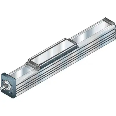
продукта. Конструкция и принадлежности. Конструктивное исполнение. 1 Шарико-винтовая передача (ШВП) с беззазорной цилиндрической одинарной гайкой. 2 Торцевой блок фиксированного подшипника. 3 Защитная лента для MKK-040/-065/-080/-110/-140. 4 Каретка с блоками качения. 5 Крепление ленты. 6 Торцевая пластина плавающего подшипника. 7 Основной корпус
8 Кронштейн переключателя. 9 Бесконтактный переключатель. 10 Механический переключатель. 11 Кабельный канал. 12 Штекер/разъём. 13 Сильфонное защитное покрытие для MKK-165. 14 Магниточувствительный датчик. 15 Кронштейн. 16 Серводвигатель. 17 Боковой привод с зубчатым ремнём. Крепление двигателя с кронштейном и муфтой. Двигатель может быть прикреплён с помощью кронштейна и муфты ко всем линейным модулям, оснащённым шарико-винтовой передачей. Кронштейн служит для крепления двигателя к линейному модулю и выполняет роль закрытого корпуса для муфты. Муфта передаёт крутящий момент двигателя без деформирующих напряжений на приводной вал линейного модуля. Наши стандартные муфты компенсируют тепловое расширение системы. 1 Двигатель. 2 Кронштейн. 3 Муфта. 4 Линейный модуль. Крепление двигателя через боковой привод с зубчатым ремнём. На всех линейных модулях с шарико-винтовой передачей двигатель может крепиться через боковой привод с зубчатым ремнём. Это делает общую длину меньше, чем при креплении двигателя с кронштейном и муфтой. Компактный закрытый корпус шкива обеспечивает защиту ремня и служит кронштейном двигателя. Кроме того, доступны различные передаточные числа. Боковой привод с зубчатым ремнём может быть смонтирован в четырёх различных направлениях. 1 Корпус шкива из анодированного алюминия. 2 В некоторых случаях с опорным подшипником для цапфы винта шарико-винтовой передачи Rexroth. 3 Линейный модуль. 4 Ремённый привод с передаточным числом: i = 1; i = 1,5; i = 2. 5 Серводвигатель. 6 Предварительное натяжение ремённого привода: Приложите усилие предварительного натяга Fpr к двигателю (Fpr указывается при поставке). 7 Крышка. 8 Шкивы ремня, закреплённые с помощью натяжных устройств. 9 Крышка-пластина.
| Параметр | Значение |
|---|---|
| Часто фактически оговаривается только | 50 000 |
| Для сравнения: Умножьте значения C, Mt и ML из таблицы на | 1,26. |
| Fcomb, Fm примерно до | 20 % |
| Lca мм | 400. |
Общие технические указания. Примечание по динамической грузоподъёмности и моментам нагрузки. Определение динамической грузоподъёмности и моментов нагрузки основано на ресурсе хода 100 000 м. м. Допустимые нагрузки. Относительно желаемого номинального ресурса, в целом нагрузки для от динамических характеристических значений (C, Mt, ML) обычно зарекомендовали себя как подходящие. См. документ «Расчёт» в главе «Указания по проектированию» для соответствующего линейного модуля. Не превышайте технические данные для системы линейного перемещения. Точка приложения эффективного усилия (Z1). Модуль упругости E системы линейного перемещения. Общие технические указания. Расчёт длины системы линейного перемещения. 1) с защитными сильфонами. Значения для расчёта длины см. в таблице «Общие технические данные». Примечание: Соблюдайте раздел «Общие технические указания» и документ «Расчёт» в главе «Указания по проектированию». Грузоподъёмность и моменты. Типоразмер MKK-165. Количество кареток 1. d0 x P м
Бесплатная доставка по РФ при заказе от 50 000 р.
Компания ООО «Индатэк» работает с юридическими лицами по всей территории России. Каждый день мы осуществляем доставку заказов от Калининграда до Владивостока. Вместе с отгруженным товаром, клиент получает бухгалтерские и гарантийные документы на 12 месяцев. По желанию, вы можете продлить срок гарантии.
При заказе от 50000 руб.
Цены указаны с НДС
И постгарантийное обслуживание