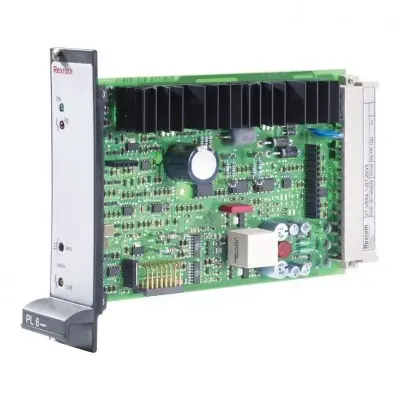
Артикул: rx7116
Бренд: Bosch Rexroth
| Параметр | Значение |
|---|---|
| Последующий ограничитель [7] ограничивает задающий сигнал до | 105 % |
| Путь | 100 % |
| В на измерительном гнезде фактического значения и на контакте | 32 |
| Вход разрешения При сигнале > | 10 В |
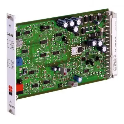
Комплектация 1X Аналоговый, формат Еврокарта Для клапанов: 2FRE 6 Особенности Дифференциальный вход, переключаемый с входа по напряжению на вход по току Два неизолированных входа задающего сигнала Вход разрешения и вход "отключения разгона" Амплитуда, нулевая точка и регулируемое время разгона Защита от переполюсовки рабочего напряжения Выходы задающего сигнала и фактического значения Светодиодная индикация "готовность к работе" Описание продукта Ограничение и регулятор положения С выхода генератора разгона [3] напряжение задающего сигнала поступает на потенциометр "Gw", доступный через переднюю панель и служащий аттенюатором. Он также может использоваться для установки максимального расхода клапана. или –5 % (например, при чрезмерном напряжении задающего сигнала или при регулировке потенциометра нулевой точки "Zw" и базового значения "Gw") для предотвращения удара золотника клапана о механические конечные положения. Выходной сигнал ограничителя [7] является задающим сигналом положения, который подается на ПИД-регуляторы [8] и через выходной каскад [17] также на измерительное гнездо "w" на передней панели платы, а также на контакт 28c клеммной колодки X1 (задающий сигнал после разгона и ограничителя). Напряжение +6 В на измерительном гнезде задающего сигнала "w" соответствует задающему сигналу +. ПИД-регулятор специально оптимизирован для клапанов DBETR и FRE. В регуляторе сравниваются задающий сигнал положения и фактическое значение положения; при наличии разницы на выходной каскад тока [13] подается соответствующий управляющий сигнал, выходной сигнал которого управляет пропорциональным электромагнитом клапана. Измерение положения Электроника датчика положения состоит из генератора [14] с последующим драйвером [15] для управления индуктивным датчиком положения и демодулятора [16] для анализа сигнала датчика положения (фактическое значение). Частота генератора составляет прибл. 2,5 кГц. Индуктивный датчик положения должен быть подключен как дроссельная цепь со средним отводом. Электроника датчика положения настроена на заводе. Очень длинные или емкостные линии датчика положения могут потребовать перенастройки нулевой точки (через потенциометр "Zx"). Фактическое значение (соответствует положению золотника клапана) можно измерить на измерительном гнезде фактического значения. Примечание: Сигнал фактического значения выводится в инвертированной форме по сравнению с задающим сигналом. 100 % соответствует –6 a клеммной колодки X1. на входе разрешения 20a выходной каскад и И-регулятор разрешены (индикация желтым светодиодом на передней панели). При установке перемычки X3 они независимо и постоянно разрешены сигналом на входе разрешения. Переключающий вход тогда неэффективен. [ ] = Привязка к блок-схеме При использовании внешнего потенциометра времени внутренние потенциометры времени разгона должны
Бесплатная доставка по РФ при заказе от 50 000 р.
Компания ООО «Индатэк» работает с юридическими лицами по всей территории России. Каждый день мы осуществляем доставку заказов от Калининграда до Владивостока. Вместе с отгруженным товаром, клиент получает бухгалтерские и гарантийные документы на 12 месяцев. По желанию, вы можете продлить срок гарантии.
При заказе от 50000 руб.
Цены указаны с НДС
И постгарантийное обслуживание